How to use BBRouter
BBRouter lets you build electronic circuits on a breadboard on your screen, switch them on, and see what they do, before you build them for real. You can't burn a part or short a battery here, so try things out.
Your screen
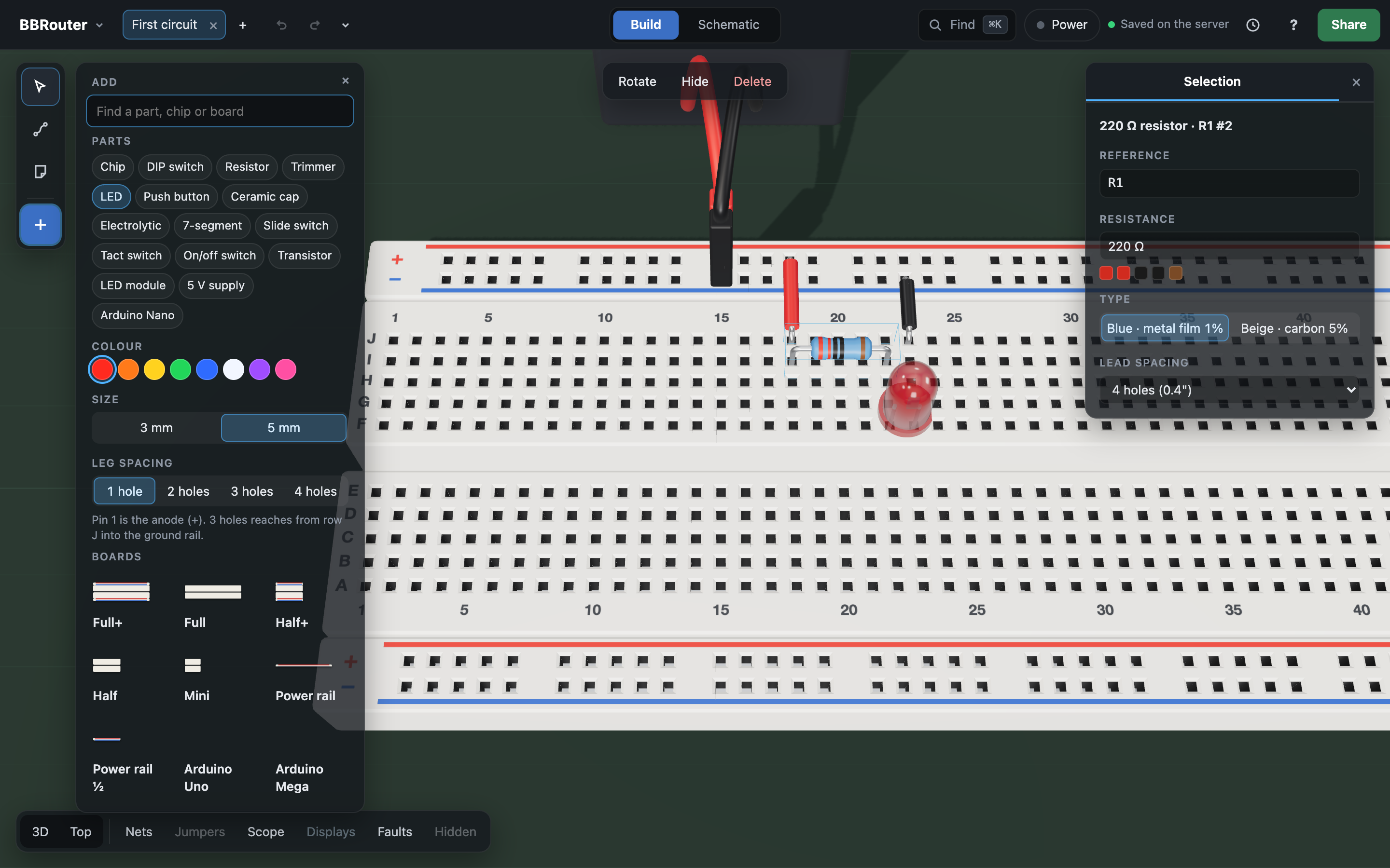
- The top bar. On its first line, the bbrouter menu (files, saving, exporting) and the project you're in, with whether it's Private or Public. On its second, your open files as tabs, Undo and Redo, Build and Schematic, Find, Power, and Share.
- The tools, on the left. Select (V) picks and moves things. Wire (W) draws wires. Note (N) pins a note on the board. + opens the library: the parts and boards you can add.
- The panel, on the right. It shows what you selected, with its settings. Its tabs also hold the Nets, your Notes and the Controls of a running circuit.
- The buttons at the bottom. 3D and Top change the view. Nets, Jumpers, Scope, Displays, Faults and Hidden each show or hide one thing.
Looking around: drag with the middle mouse button (or drag an empty spot) to turn around the board, drag with the right button to slide it, and scroll to zoom. Top looks straight down, which is easiest for wiring.
How a breadboard works
A breadboard is full of holes, and metal clips under the holes join some of them together. Parts in joined holes are connected, without any soldering.
- Strips. Each short column of 5 holes is one strip: the 5 holes are joined. The strips are numbered along the board, and the rows are lettered A to J.
- The channel. The gap down the middle splits each column into two strips, A–E and F–J. Chips sit across it, so each of their pins gets its own strip.
- The rails. The long lines along the edges, marked + (red) and − (blue or black), are joined all along. They carry the power: + is 5 volts and − is ground (0 volts).
Your first circuit: light an LED
You'll build the "hello world" of electronics: a light-emitting diode (LED) that turns on when the power does.
- Start a new file. Open the bbrouter menu and choose New file. Give it a name and press Create. You get one empty breadboard.
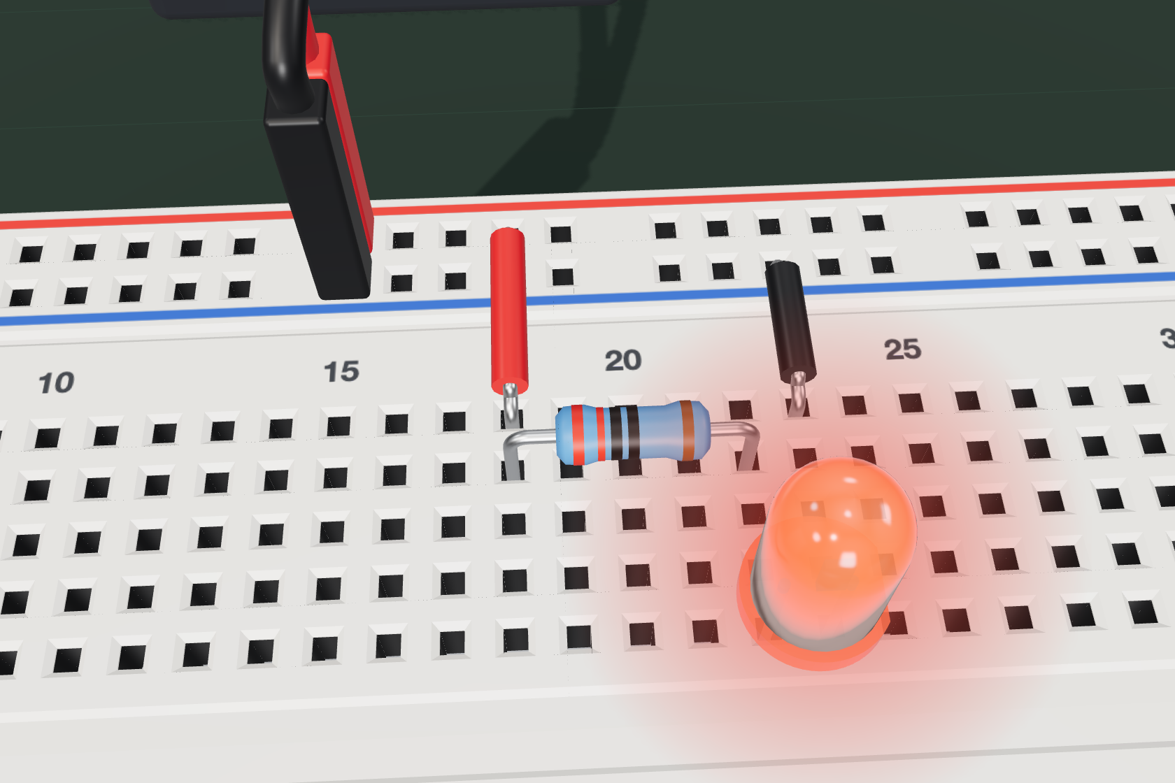
- Add the power. Press P (or click +) to open the library. Under Parts, click 5 V supply, then click a hole on the top + rail. Its red lead goes in + and its black lead in −, the rail just below.
- Add a resistor. In the library, click Resistor, then click a hole in row I, the second row from the top rails (for example I18). Its other lead lands 4 holes along, in I22. A resistor slows the current down, so the LED doesn't get too much.
- Add an LED. Click LED, then click the hole in row F under the resistor's second lead (F22). Holes F to J of a strip are joined, so the LED's first leg, its long leg (the + side, called the anode), touches the resistor. Its short leg lands in the next strip (23).
- Draw two wires. Press W for the wire tool. Click the hole on the + rail right above the resistor's first strip, then the top hole of that strip (J18): that's one straight wire. Then wire the top hole of the LED's short-leg strip (J23) to the − rail hole right above it. Press Esc when you're done.
- Switch it on. Click Power in the top bar. The LED lights up. Click Power again to switch it off.
It didn't light up? Check that the LED's long leg is on the resistor's side, that every lead is in a hole (a red lead end means it isn't), and that both wires are in the right strips. The Faults button (see below) can help.
Parts
Open the library with P or +. Parts lists the parts you can place, and Boards the breadboards. For a real chip, click Chip, then pick which one (like 74LS00) in the list below. The list groups them by family: 74LS, 74HC, CD4000 (CMOS chips, like the CD4011 or CD4017) and others such as the 555. Or type a name or chip number in the search box to find it quickly.
- Place: click a part in the library, then click a hole. It follows the pointer until you drop it.
- Move: with Select (V), drag it. Drag a lead's end to move just that lead to another hole.
- Turn: press R (or ⇧ R to turn the other way).
- Copy, paste, delete: ⌘ C, ⌘ V, ⌘ D (duplicate), and ⌫ (Backspace) to delete.
- Settings: select a part to see its settings in the panel, like a resistor's value, an LED's color, or a chip's number. Its Reference (like R1 or U3) is its name in the circuit: two parts can't share one.
Some parts you'll use:
- Resistor: limits how much current flows. Its colored bands show its value, in ohms (Ω).
- LED: lights up when current flows from its long leg (+) to its short leg (−).
- Push button: connects while you hold it down. While the power is on, press its round cap to press it; grab its body to move it.
- Slide switch, On/off switch, DIP switch: click them to flip them.
- Trimmer: a knob you turn to change a resistance.
- Capacitor (ceramic or electrolytic): stores a little charge. With a resistor it can set how fast something happens.
- 7-segment display, LED module: many LEDs in one part, to show digits or a row of lights.
- Chip: a whole circuit in a little black box. Pin 1 is marked by a dot or a notch.
Wires
Press W to draw wires.
- Click the hole where the wire starts.
- Click where you want it to turn, if it should go around something (or ⇧-click). ⌫ takes back the last turn.
- Click the hole where it ends.
Select a wire to change its color, its size, or to make it a Dupont jumper (a flexible wire with plugs). Colors don't change how a circuit works, but they help you read it: red for +, black for −, and your own colors for the rest.
Chips
A chip has many pins, numbered around it starting from pin 1, next to the dot or notch. Hover over a chip, or select it, to see the name of each pin.
- Every chip needs power. Its VCC pin goes to + and its GND pin goes to − (on a CD4000 chip, VDD and VSS), with wires to the rails. Without them, nothing happens and BBRouter warns you.
- Look it up. Select a chip to see what it does, and open its datasheet (its official instructions) from the panel.
- Inputs and outputs. An input pin reads a signal, and an output pin makes one. Two outputs wired together fight each other, which is called a short.
Running your circuit
Click Power to switch the circuit on. BBRouter runs it as if it were real:
- LEDs light up, and displays show their digits.
- Buttons and switches work: press or flip them with the mouse.
- Clocks tick. A 555 timer chip with its resistors and capacitor makes a steady beat.
- The Controls tab shows what's happening, with any warnings.
⏸ pauses the circuit, and Power again switches it off. Your work is never lost when you switch it off.
Seeing signals with the scope
A digital signal is either high (5 V, a 1) or low (0 V, a 0). The Scope shows how signals change over time, like a real oscilloscope.
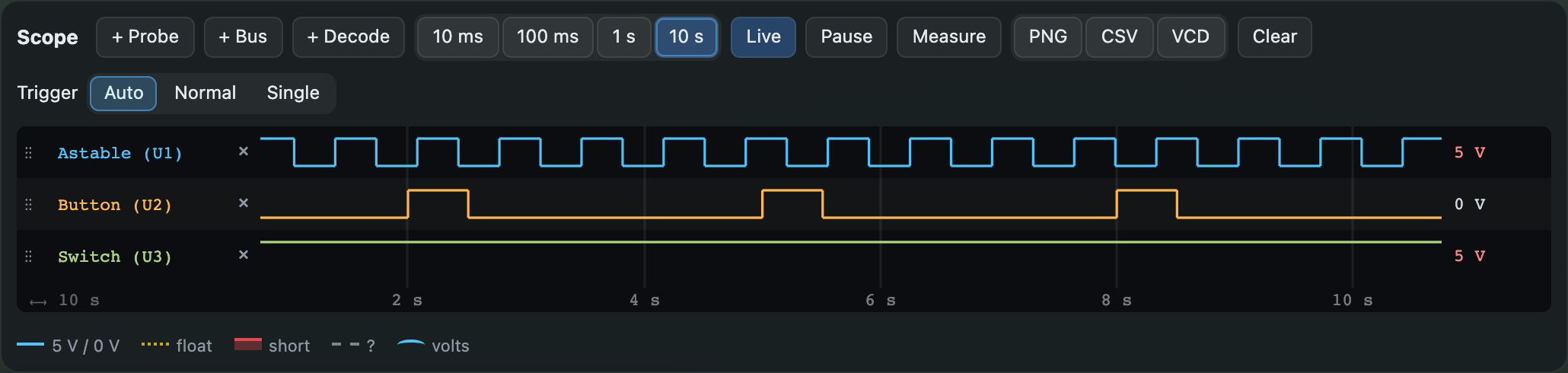
- Click Scope at the bottom, then + Probe, then click a hole. That adds a lane for it.
- Switch the power on. Each lane draws its signal: up for high, down for low.
- Choose how much time to show: 10 ms, 100 ms, 1 s or 10 s.
Besides high and low, the scope shows two problems:
- float (an amber dotted line): nothing drives that line. A chip's input left unconnected reads it as high, but only by accident.
- short (a red band): two outputs fight over that line, one high and one low.
Some holes have a voltage rather than a level: a 555's timing capacitor charging and discharging, a capacitor turning a clock edge into a short pulse, a trimmer's middle pin. Their lane is taller and draws the voltage as a curve between 0 V and the supply, with dashed lines where the chips reading it switch. The value beside it, the cursors and Measure say volts, and the trigger can fire as it rises or falls through a voltage. Hover such a hole on the board to read, say, 3.27 V (charging).
Finding mistakes
- Faults. With the power on, the Faults button counts the shorts (red) and floating lines (amber). Click it to circle every pin on them, and to list them in a pane. Click a line in the list to look at it.
- Nets. A net is a group of pins that should all be connected. The Nets panel shows which connections are still missing, which wires join nets that should stay apart, and which wiring isn't in any net. Show where points to each problem on the board.
- Undo. Made a mistake? ⌘ Z takes back your last change, and ⌘ U (or ⇧ ⌘ Z) puts it back.
Saving, versions and sharing
- Saving is automatic. Every change is saved on the server as you go. The top bar says Saved on the server.
- Projects. Your files are kept in projects; everyone has one called default. Open… (in the bbrouter menu, or click the project's name) lists your projects and their files: make a New project, move a file to another one, rename or delete them. A new file goes in the project you're in.
- Addresses. Each file has its own address, like app.bbrouter.io/yourname/default/My-clock (spaces become dashes), to bookmark or open in another tab. A project's address opens it with its files to pick from.
- Public projects. Click Private next to the project's name to make it public: anyone with its address can then look at every file in it, read-only, run it, and save a copy of their own. Click Public to make it private again.
- Versions. The clock button in the top bar keeps named versions of your file, like "LED works". You can go back to one at any time.
- Try a change safely. Branch to try a change (in the bbrouter menu) makes a copy next to your file. Try your idea there, then Commit it into your file, or Discard it.
- Notes. Press N and click to pin a note on the board, to explain your circuit or ask a question.
- Share. Share copies a link (app.bbrouter.io/s/…) to exactly what you're looking at, with your notes. Anyone with the link can open it, read-only, even without an account; to change it, they save a copy of their own. Stop sharing makes every link to the file stop working.
Building it for real
When your circuit works on screen, BBRouter helps you build it on a real breadboard:
- Build sheet (in the bbrouter menu): a printable sheet with every part and wire, step by step, and a shopping list.
- Bill of materials: the list of parts to buy, as a spreadsheet.
- Your real breadboard looks just like the one on screen, so you can copy it hole by hole.
Going further
- Schematic. Schematic in the top bar shows your circuit as a diagram, the way engineers draw it.
- Arduino. Place an Arduino board (Nano, Uno or Mega), upload a program (a sketch) to it from the Arduino IDE, and watch it run with your circuit.
- Chips that remember. Registers, counters and memory chips show and set what they hold, in the panel, while the circuit runs. A virtual display can show a value floating over the board.
- Bigger projects. You can build a whole computer, like the 8-bit computer by Ben Eater, one module at a time.
Keyboard shortcuts
Press ? in the app to see them all.
- ⌘ K: find an action, part or file
- P: open the library of parts
- V, W, N: the Select, Wire and Note tools
- R: turn the selected part
- ⌘ Z and ⌘ U: undo and redo
- ⌘ C, ⌘ V, ⌘ D: copy, paste, duplicate
- ⌫: delete what's selected
- H: hide what's selected (or show it again)
- Esc: cancel, or close
Words to know
- Breadboard: a board full of holes for building circuits without soldering.
- Circuit: a path that electricity can flow around.
- Current: how much electricity flows, in amperes (A).
- Voltage: the push behind the current, in volts (V). Here, + is 5 V and − is 0 V.
- Ground: 0 volts, the − rail. Every circuit needs a way back to it.
- Resistor: a part that limits current. Its value is in ohms (Ω).
- LED: a light-emitting diode. It lights when current flows from + to −.
- Chip (or integrated circuit): a whole circuit inside a small package with pins.
- Pin: one of a chip's metal legs.
- High and low: the two levels of a digital signal, 5 V (1) and 0 V (0).
- Clock: a signal that goes high and low again and again, to keep time.
- Net: a group of pins that are all connected together.
- Bus: a set of wires that carries a number, one bit on each wire.
- Short: two outputs fighting over the same line, one high and one low.
- Floating: a line that nothing drives, so its level is a guess.